Verifying and troubleshooting cables, connectors and antennas
By Rolland Zhang, Agilent Technologies
Monday, 04 February, 2013
Cable and antenna measurements are often used to verify and troubleshoot the electrical performance of RF and microwave transmission systems and antennas. Key to ensuring fast, accurate and efficient cable and antenna testing (CAT) is use of appropriate instrumentation and the right measurement techniques.
Roughly 50 to 60% of cellular base station problems are caused by faulty cables, connectors and antennas. Components may become damaged during installation, operation and maintenance of a telecommunication system or show reduced performance over time. Damage can also result from the extreme weather conditions to which many outdoor installations are exposed.
Even sheltered installations can be problematic, potentially exposing components to mishandling, stress, heat, vibration and containments that can leak into the system. Such failures cause poor coverage and unnecessary handovers in the cellular system, making appropriate testing all the more critical.
CAT basics
When verifying and maintaining the operation of RF and microwave transmission systems and antennas, measurements are often made along the coaxial cable connecting a transmitter to its antenna and/or between an antenna and its receiver.
This process, line sweeping, measures signal attenuation or insertion loss and return loss as a function of frequency. Line sweeping is also used to estimate the physical location of a fault or damage along the transmission line using the distance to fault (DTF) measurement available on many RF and microwave signal analysers.
Testing transmission line performance is not only limited to coaxial cable types. Systems using waveguide and twisted pair cables may also be characterised once the appropriate adapter is installed between the transmission line and the coaxial interface on the analyser.
In addition, antenna measurements, in the form of signal reflection or return loss and voltage standing wave ratio (VSWR), may be used to verify the performance of an antenna at the installation site. When multiple antennas are required at a site, antenna-to-antenna isolation may also be verified.
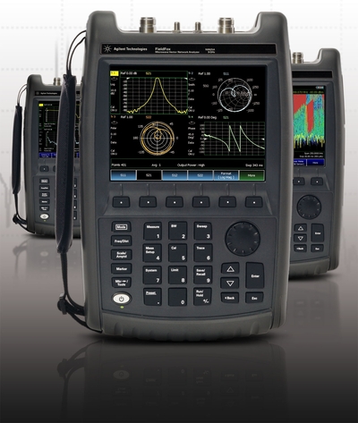
In all cases, a modern handheld microwave analyser configured for cable and antenna testing proves especially effective for making the required measurements (Figure 1). Its performance, functionality and flexibility make it a useful tool for quickly and accurately characterising the entire transmission system, as well as the performance of individual components in the system.

Tackling cable insertion loss
The insertion loss of transmission line or coaxial cable, often measured as a function of the intended operating frequency band, is the amount of energy dissipated in the cable and includes energy lost due to mismatch reflection between the source and load.
Generally, the source (transmitter), transmission line (coaxial cable) and load (antenna) are all designed for the same characteristic impedance, Zo - usually 50 or 75 Ω when using coaxial cable. Most modern RF and microwave analysers are configured with 50 Ω test port impedances. When measuring 75 Ω cables and components, a 50 to 75 Ω adapter is required.
Removing transmission line cables to verify their operation and troubleshoot cable failures once they have been installed in a system is costly and difficult. With very long cable runs, access to both ends of the cable at the same time is typically impossible, especially when attempting to connect the cable to the test instrumentation. Under these conditions, techniques for measuring cable insertion loss from one end of the cable are preferred.
Three techniques for measuring cable insertion loss with a modern RF and microwave analyser in CAT mode are:
Two-port technique: Here the cable under test is connected to two separate ports on the analyser. The analyser injects a test signal into the cable from its RF OUT port. As the signal passes through the cable, a small portion of the energy is absorbed by resistive and dielectric losses in the cable. Discontinuities from cable connectors, cable splices, damage and other factors reflect a portion of the energy back to the source resulting in an additional increase in measured insertion loss. The remaining signal exiting the cable is then measured by the analyser at the RF IN port. The ratio between input and output signals represents the total insertion loss of the cable usually expressed in decibels (dB).
One-port technique: This method measures cable insertion loss from only one end of the cable under test. One end of the cable is attached to the analyser, while the other is left open or terminated in a short (recommended for microwave frequencies). The analyser injects a test signal into the cable from the RF OUT port. The signal passes through the cable, is completely reflected from the open (or shorted) end, passes through the cable a second time, and is measured by the analyser using the same port. The analyser then uses this information and a built-in model for coaxial cable dispersion to report cable insertion loss as a function of frequency. This technique is only available on analysers configured with an internal factory-calibrated reflectometer for measuring reflected signals at the instrument’s RF OUT port.
Power-meter technique: With this technique, the instrument is configured as a power meter connected to a USB power sensor. One end of the cable under test is connected to the analyser’s RF OUT port, while the other end is connected to the USB power sensor. The analyser is configured to generate a CW signal at the RF OUT port. This test signal is transmitted along the cable and measured by the USB power sensor. If the cable ends are separated by a large distance, the sensor is connected back to the analyser through a USB cable extender. Because this technique does not allow swept-frequency measurements, manual tuning of the analyser’s settings is required when changing test frequencies.
When measuring cables with high insertion loss, the displayed measurement trace may exhibit a high level of noise. In this case, the relative signal-to-noise and associated measurement accuracy can be improved by setting the analyser’s output power to high-power mode. The displayed noise level can also be reduced by increasing the number of trace averages or decreasing the intermediate frequency bandwidth setting.
Measuring antenna return loss and VSWR
Antennas are specified by their gain factor and return loss or VSWR. Antenna gain measurements are typically performed in a special test facility (eg, an anechoic chamber).
Return loss and VSWR are standard measurements reported for most RF and microwave components and systems and can easily be measured with a modern microwave analyser in the field or lab.
Once installed in a system, only an antenna’s reflection properties are measured to determine whether or not it is faulty or damaged. The antenna’s return loss and VSWR are used to characterise its performance. These one-port measurements are typically performed over the intended frequency band of interest.
A typical antenna with a return loss of 10 dB or higher represents a reasonably well-matched antenna. A 10 dB return loss is equivalent to having 90% of the incident energy radiated by the antenna and 10% of the energy reflected back to the transmitter.
For applications where high efficiency is required (eg, base station antennas), the return loss may be specified at 15 dB or higher. A 10 dB return loss is about equal to a VSWR of 2:1.
While a conversion table can be used to find the relation between values of return loss and VSWR, some modern analysers handle this conversion and can be easily configured to display the measured response as return loss or VSWR.
When interfacing the antenna to the analyser, high-quality adapters can be used to improve measurement accuracy and repeatability. The adapter characteristics may be removed from the measured results using the analyser’s calibration feature. The analyser should also be attached as close to the antenna as possible so the insertion loss of the cable does not mask the antenna’s true return loss.
Verifying antenna-to-antenna isolation
When different wireless systems are co-located to share tower and shelter structures, antennas (either operating within the same system or between different systems) must be spaced far enough apart to maintain an adequate level of isolation. This prevents creation of intermodulation distortion in the transmit amplifiers and/or noise desensitisation in the receivers.
Systems are typically designed with duplexing and other filters to reject signals from nearby transmitters and other interference, but system performance may require an antenna-to-antenna isolation of 60 dB or more. It is therefore necessary to sweep the antenna-to-antenna isolation across all frequency bands of interest. This can be done with a two-port insertion loss measurement in which each antenna is attached via a short jumper cable to the analyser.
Locating faults
When cable insertion loss is higher than expected or return loss and VSWR is out of specification, finding fault locations along the transmission system becomes essential. The location is determined using the analyser’s DTF capability, which uses reflection measurements taken from the transmission line to calculate the individual amplitude response of any discontinuities as a function of distance.
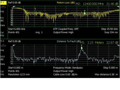
Figure 2 shows a dual display of the return loss as a function of frequency and associated DTF measurement from a section of coaxial cable connected to an antenna. When examining the DTF display, high amplitude level signals are located at the points where discontinuities exist along the transmission line and at the load.
The location of these high amplitude signals provides an important troubleshooting tool when determining faults in the cabled transmission system.

A typical configuration for measuring DTF is shown in Figure 3. It is assumed that the load (eg, the system antenna, a 50 Ω termination or just an open-ended cable) is connected to the analyser through two sections of coaxial cables connected via an adapter.
Figure 3 also shows a table of important cable specifications as supplied by the manufacturer. The specification for velocity factor (VF) is important to enter into the analyser for the instrument to correctly display the distance to each cable discontinuity.

DTF measurements of transmission systems are primarily concerned with locating the physical position of faults along the line and, therefore, precise amplitude measurements of the return loss and VSWR may not be required.
Accordingly, most applications only require that the cable’s VF be entered into the analyser’s cable specification table. When the VF of a cable is unknown but the physical distance of the cable is known, it can be estimated using the DTF measurement.
Conclusion
Cable and antenna testing is critical to verifying and maintaining the operation of RF and microwave transmission systems and antennas. Use of appropriate measurement and calibration techniques, along with a modern RF and microwave signal analyser configured for cable and antenna testing, provides the best means of accurately, quickly and effectively accomplishing this goal.
'Cooperative Lift' enables drone teams to share heavy loads
Cooperative Lift technology enables Freespace Operations' heavy-lift drones to work together...
Ultra-compact radio module enables 6G applications
An ultra-compact, low-power, 150 GHz radio module enabling high data rates in mobile devices has...
Eastern Goldfields Railway signalling upgrade completed
The project has seen a substantial advancement in the signalling technology utilised along a...


