A roadmap for RF coverage testing
Monday, 16 April, 2012
Government initiatives like the national interoperable mobile broadband network, narrow banding and legacy migration to P25 digital are making coverage testing a required part of the wireless communication system engineering cycle. In addition, legislation is emerging which codifies indoor coverage. These regulations are motivated by the need to improve spectral efficiency, better allocate field assets and assure the safety of first responders.
The wireless system in place may be adequately meeting the needs of the agency; however, technology changes and federal or local legislation require that this existing system be replaced or significantly changed.
In these cases, the system designer must: benchmark the coverage of the existing system; specify the new system, based on existing coverage performance; and test the new system to meet coverage specifications.
Most system operators are familiar with the signal strength test for analysing the signal quantity of a wireless system over an area of intended coverage. This has long been the standard for new system compliance tests. However, the ultimate test of a signal is not quantity, but quality - the ability to communicate, which can be measured in SINAD for analog and BER for digital systems.
Drive test packages, such as STI Field Test 7, automate over-the-air measurements while driving or travelling throughout an area of interest. The test system can be set up to combine many types of measurement data with time and location in a measurement database, which can then be analysed for a variety of purposes.
Testing signal quality
Digital
Signal quality for digital signals is measured by Bit Error Rate (BER). BER and signal strength measurements combined, during drive tests, provide wireless engineers with an indication of the quality of the wireless link across the service area tested. Transmitters are usually equipped to create a known bit pattern for tuning and testing their performance. These patterns can be transmitted over the RF link and received, decoded and analysed for accuracy.
Some manufacturers’ P25 radios have the ability to decode a standard pattern and provide a BER. Also, some manufacturers of digital radio test sets have developed highly sensitive instruments that can decode BER off the air. System engineers must determine whether they want a calibrated instrument conducting this analysis or if they are testing the ability of a radio to receive and decode the signal around the service area. Both are valid tests. Digital radio test set and subscriber unit solutions are both used for analysing the digital signal quality of wireless systems, such as P25 systems.
Drive tests of signal strength and BER, concurrently, are the best way to measure the performance of a digital voice link.
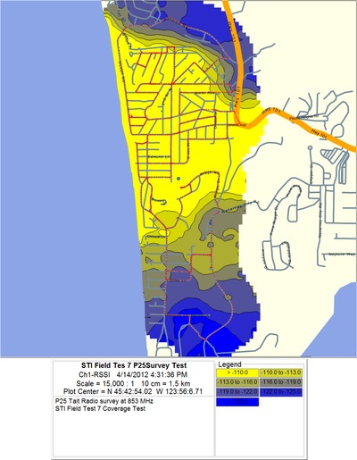
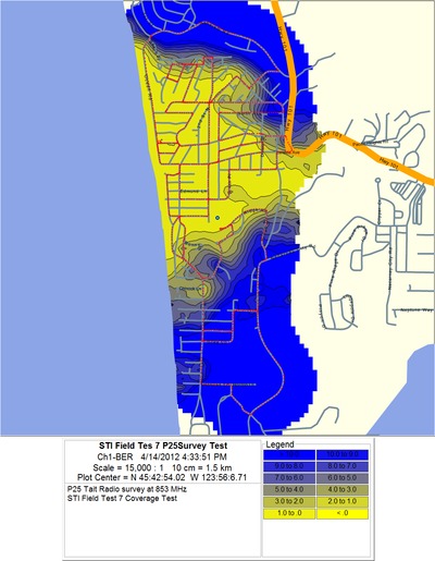
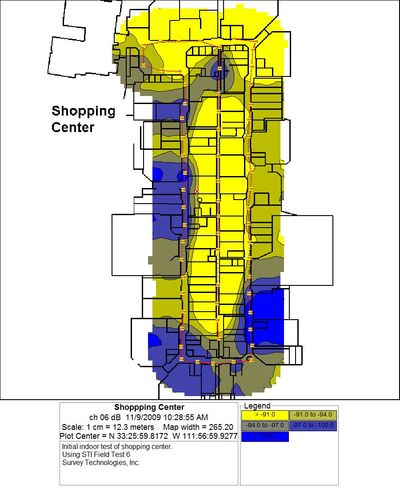
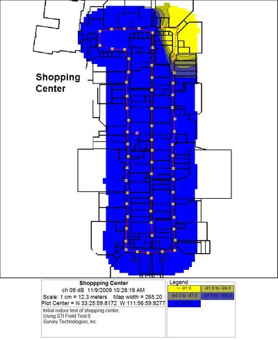
Comparing the two reports shows a small area, about one third of the way from the bottom, where a very slight drop in signal strength results in a disproportionately large drop in signal quality (BER). A small hill to the north causes only a small attenuation in signal strength. However, the signal quality is greatly affected due to distortion of the signal around the edges of the hill.
Analog
Signal quality for analog signals is measured by SINAD. Engineers with analog voice link interests can use a drive test package, such as STI Field Test 7, to make audio SINAD measurements of a two-tone signal being transmitted over their voice link. The engineers' test radio receives the signal and the test system digitises the signal across the radio speaker or ear piece.
An FFT is performed on the audio sample to convert the time sample to a frequency spectrum. The power of the desired two tones (Ssgnal) is then compared to the power outside of the two tones (noise and distortion).
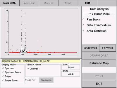
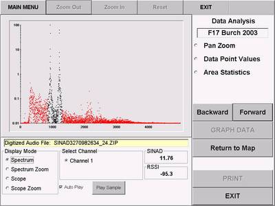
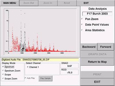
Signal strength, along with audio SINAD measurements, is the best way to analyse the performance of an analog voice link.
Distortion
Signal quality measurements, such as SINAD or BER, will uncover areas of signal distortion or co-channel interference, where signal strength is high but quality is reduced. This allows the system designer to take action to counteract the effects of the distortion.
Testing system compliance
Compliance testing is one of the major reasons that system engineers are mandating drive tests. Performance specification and methodology are the most important part of a new system acceptance plan. A testing methodology, including a tile analysis of the test results, can be used to quantify the coverage of the system.
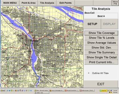
After data collection, the area of interest can be analysed statistically using analysis based on rectangular tiles. A verifiable specification statement for a communications system, using this quantitative form of analysis, might read: “Tile sizes will be 30 second rectangles. After qualifying 80% of the tiles in this geographic area with at least 10 measurement samples, at least 95% of the qualified tiles must have 100% of their measurements above -95 dBm.” STI Field Test 7 allows each of these variables to be customised for user requirements. This allows for an objective standard when writing contracts for system development and compliance testing of the performance of that system.
Testing indoor coverage
In many urban areas, public spaces such as transit stations, arenas, large shopping centres, schools and government buildings are now required to have a specified level of wireless coverage or performance. This is becoming more common as national, state and local governments are increasingly aware of the need for reliable communication in the face of potential disasters.
How are these requirements satisfied? The indoor testing option on STI Field Test 7 software provides the ability to perform tests where GPS reception is unavailable. The user provides a building plan, as a background map, and specifies a measurement route on the plan. Measurements are performed while travelling between points on the measurement route. Field Test 7 then locates the points geographically and uses the recorded measurements to create contour plots.
Testing uplink
Uplink testing is important for two reasons. First, there is a difference in portable versus site transmitted power, which means the transmission from the mobile to the site (the uplink) is, typically, a weaker link. Second, the uplink and downlink in a voting receiver network architecture use completely different radio links.
For uplink testing, a mobile, in a test vehicle, transmits to the site. Its position and the time of the transmission are recorded in one database. Meanwhile, the test system at the site is measuring signal characteristics, logging measurements and the time of each measurement. After testing is complete, the STI GPS Timer application can combine these two databases, based on time, and contour plots of measurement value over geography can be created.
If intermittent measurements are required, the GPS Timer application can be employed to synchronise transmission and measurement times and combine the databases after the measurements are complete.
Testing with GPS timer and push-to-talk (PTT) switch
In cases where a transmitter cannot be turned on full time, a synchronised measurement is required. This special technique is enabled by a GPS Timer application and an external computer-controlled relay (PTT switch). The GPS Timer application is implemented as a separate standalone software application, or as an optional driver extension that can be added to several Field Test 7 drivers. These applications synchronise to GPS time of day and control measurement start and stop times, transmitter on and off time and the total cycle time.
The PTT switch is a hardware option which allows the user to energise a mobile transmitter through a relay closure.
Hang time testing
The PTT switch activates a mobile transmitter, which causes a site transmitter to respond. The measurement is made immediately after the PTT switch deactivates the mobile transmitter and during the hang time of the site transmitter.
Synchronised testing
The GPS timer application and PTT switch hardware activate a site transmitter at the same intervals that the mobile test unit is directed to make measurements by the GPS timer driver extension.
These STI-9400 hardware options allow measurements and the test signals to be synchronised to GPS time of day at different locations.
Coverage prediction
Many propagation software packages have the ability to import and display drive test measurements so that an ‘actual vs. predicted’ analysis of signal strength may be performed. The method of using drive test measurements to calibrate a predictive result is especially useful when planning a wireless system expansion.
The existing system’s actual signal coverage can be measured and compared to the existing system’s predicted coverage. If necessary, the prediction can be adjusted to more accurately reflect existing measured coverage. This increases confidence in projected coverage for system changes or expansion.
In this way, models of the existing system are made with planning software, calibrated against drive test measurements and used to plan the system expansion. To assure communication critical to the safety of our first responders, drive test measurements of signal quality, as well as signal strength, are essential steps in system design, construction and validation.
Using AI to build your next-gen wireless system
The central challenge engineers face when designing wireless systems and networks is their...
Ensuring 5G network performance
To be successful in business-critical use cases, the wireless networks need to be as reliable as...
Ubiquitous connectivity is the future of wireless
Systems capable of seamlessly using satellite, cellular and local area networks are nowadays a...


